Feedback control
DRT 344 Automation, Robotics and Intelligent Control Systems
Lesson
By the end of this module you will be able to
- Compare open-loop and closed-loop control
- Explain the role of the P, I and D terms and their effect on the response
- Calculate the steady-state error of proportional control
- Tune a PID controller initially with the Ziegler–Nichols method and state its limits
- Explain PX4's cascaded multicopter control and the tuning order
Why this matters
A multirotor is not inherently stable. Without a controller adjusting motor speeds hundreds of times per second, it would flip over in a fraction of a second. The controller behind almost every system, from drones and robots to air conditioners, is feedback control, and the most widely used form is PID.
Feedback control is like keeping a car in the middle of its lane. You see how far the car has drifted (the error) and turn the wheel to correct it; the bigger the drift, the more you turn. If a crosswind keeps pushing, you gradually hold the wheel over. If you see the car drifting fast, you correct in advance. These three behaviours are P, I and D.
Open loop versus closed loop
- Open loop acts on a plan without measuring the result, such as running motors at fixed power from a table. If wind or load changes, the result drifts and nothing corrects it
- Closed loop measures the real output with a sensor, compares it with the setpoint, and adjusts the command using the error
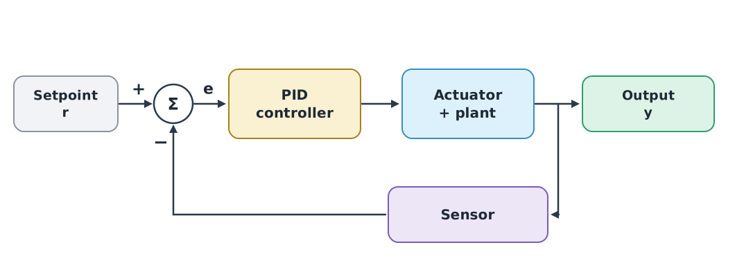
The PID controller
| Term | Responds to | Effect of increasing it | Caution |
|---|---|---|---|
| P (proportional) | The present error | Faster response | Too much causes oscillation; alone it usually leaves a residual error |
| I (integral) | Accumulated past error | Removes residual error | Too much causes oscillation and overshoot; needs anti-windup |
| D (derivative) | Rate of change of error | Damps oscillation | Amplifies noise; needs filtering |
Integrator windup happens when the actuator is saturated, for example motors at full power, while the I term keeps accumulating. When the error reverses, the controller responds very slowly, so the I term must be limited (anti-windup). PX4 does this by clamping in its velocity loop.
Example 1 Why P alone does not reach the target
A first-order plant has steady-state gain and a P controller with . For a step setpoint:
The system settles about 14.3% short of the target. Raising shrinks the error but never removes it, and a real system with delay starts to oscillate. Adding an I term removes the residual error.
Ziegler–Nichols tuning
Ziegler and Nichols (1942) proposed finding initial PID values by experiment. In one method, raise gradually (with I and D off) until the system oscillates steadily; record that gain as and the oscillation period as , then use the table (Åström & Murray, Table 11.1):
| Controller | |||
|---|---|---|---|
| P | – | – | |
| PI | – | ||
| PID |
Example 2 Calculating PID gains from an experiment
On a motor test rig, the system oscillates steadily at with period s.
- s, so
- s, so
Åström and Murray warn that the Ziegler–Nichols rules use too little process information and often give closed loops that lack robustness. These values are only a starting point, and never drive a real drone to sustained oscillation; do it only on a test rig or in simulation.
Cascaded control in multirotors
PX4 uses a cascaded control architecture, a mix of P and PID controllers in layers.
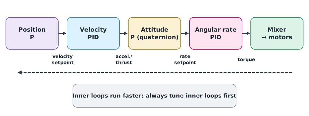
| Loop | Type | Output | Example PX4 parameters |
|---|---|---|---|
| Position | P | Velocity setpoint | MPC_XY_P, MPC_Z_P |
| Velocity | PID | Acceleration setpoint | MPC_XY_VEL_P_ACC, MPC_XY_VEL_I_ACC, MPC_XY_VEL_D_ACC |
| Attitude | P on quaternion | Rate setpoint | MC_ROLL_P, MC_PITCH_P, MC_YAW_P |
| Angular rate | PID | Torque to the mixer | MC_ROLLRATE_P/I/D, MC_PITCHRATE_P/I/D |
Inner loops run faster than outer loops. The rate loop takes filtered gyro data, and the gyro publication rate is set by IMU_GYRO_RATEMAX. The PX4 tuning guide stresses tuning the rate controller first, because it affects all flight modes; the attitude loop is then much easier. It suggests raising gains by 20–30% per iteration, then 5–10% for fine tuning, testing with fast step inputs in hover.
Class activity
Activity: Simulating an altitude controller
- Write a Python simulation of a discrete first-order plant with P, PI and PID controllers.
- Compare rise time, overshoot and residual error for each.
- Add an actuator limit and observe integrator windup, then add anti-windup.
- If available, read a PX4 SITL tuning log and identify which loop was tuned first.
Common mistakes
Watch out
- Tuning outer loops before inner loops, fixing the wrong problem
- Raising D without filtering, so motors vibrate and heat up
- No anti-windup when actuators saturate
- Treating Ziegler–Nichols values as final without checking robustness
- Driving a real drone to its stability limit during tests
Summary
- A closed loop measures the output and corrects using the error
- P reacts to the present error, I removes residual error, D damps oscillation
- P control of a first-order plant leaves
- Ziegler–Nichols PID: , , , only a starting point
- PX4 cascades P → PID → P → PID; tune the rate loop first
Check your understanding
- Which PID term removes residual error?
- A first-order plant with uses P control with . What is the steady-state error?
- An experiment gives and s. Calculate PID , and by Ziegler–Nichols.
- In PX4, which loop sends the rate setpoint to the rate loop?
- Why tune the rate loop before the others?
Answers
- The I (integral) term
- , about 11%
- ; s so ; s so
- The attitude loop, a P controller on the quaternion
- Every outer loop acts through the rate loop; if the inner loop is poor, the outer loops cannot be tuned well, and it affects all flight modes
Key formulas
| PID controller | |
| Steady-state error (first-order plant, P control) | |
| Ziegler–Nichols ultimate-gain PID | |
| Converting to gains |
Key references
- Åström, K. J., & Murray, R. M. (2021). Feedback systems: An introduction for scientists and engineers (2nd ed.). Princeton University Press. link
- Nise, N. S. (2019). Control systems engineering (8th ed.). Wiley.
- Ziegler, J. G., & Nichols, N. B. (1942). Optimum settings for automatic controllers. Transactions of the ASME, 64(8), 759–765. link
- PX4 Autopilot. Controller diagrams; Multicopter PID tuning guide. PX4 user guide (main). link
- Beard, R. W., & McLain, T. W. (2012). Small unmanned aircraft: Theory and practice. Princeton University Press.
- Quan, Q. (2017). Introduction to multicopter design and control. Springer.
Further reading
Study the assigned knowledge units in advance, review media and take the module quiz
Feedback control and PID controllers
Cascade control and flight-controller tuning
In class / field
Lecture, case discussion and in-class problem solving
Learning evidence: Quiz results and submitted exercises