Automated operations
DRT 342 Mission Planning, Autonomous Operations and Beyond Visual Line of Sight
Lesson
By the end of this module you will be able to
- Explain how an automated mission is built from MAVLink commands and flight modes
- Compare RTL and geofence behaviour in PX4 and ArduPilot
- Configure failsafes from a risk assessment rather than accepting defaults unchecked
- Calculate the energy needed for RTL and the geofence margin
- Plan SITL testing and in-flight mission monitoring
Why this matters
In an automated mission the pilot does not move the sticks every second. The autopilot follows commands written in advance, including what to do when something goes wrong. Configure it wrongly and the drone will “do the wrong thing precisely”: return home at a height below the treetops, or keep flying long after the ground station has lost contact.
An autopilot is like a driver who follows the satnav to the letter. It drives very well, but it will follow the route even if the route is wrong. The planner is responsible for both the route and the rules for when things go wrong.
An automated mission is a list of commands
PX4 and ArduPilot both store a mission as a list of MAVLink mission items. A ground control station (GCS) such as QGroundControl or Mission Planner is used to create, edit, upload and monitor the mission.
| MAVLink command | ID | Meaning |
|---|---|---|
MAV_CMD_NAV_TAKEOFF | 22 | Take off to a set altitude |
MAV_CMD_NAV_WAYPOINT | 16 | Fly to a position and altitude |
MAV_CMD_NAV_LOITER_TIME | 19 | Loiter at a position for a set time |
MAV_CMD_DO_CHANGE_SPEED | 178 | Change speed |
MAV_CMD_NAV_RETURN_TO_LAUNCH | 20 | Return to launch |
MAV_CMD_NAV_LAND | 21 | Land |
NAV commands define movement; DO commands trigger actions along the way, such as changing speed or firing the camera. Waypoint altitude must state its reference frame clearly, for example relative to home or above mean sea level, because on sloping or hilly ground the two can be very different.
Mission states and failsafes
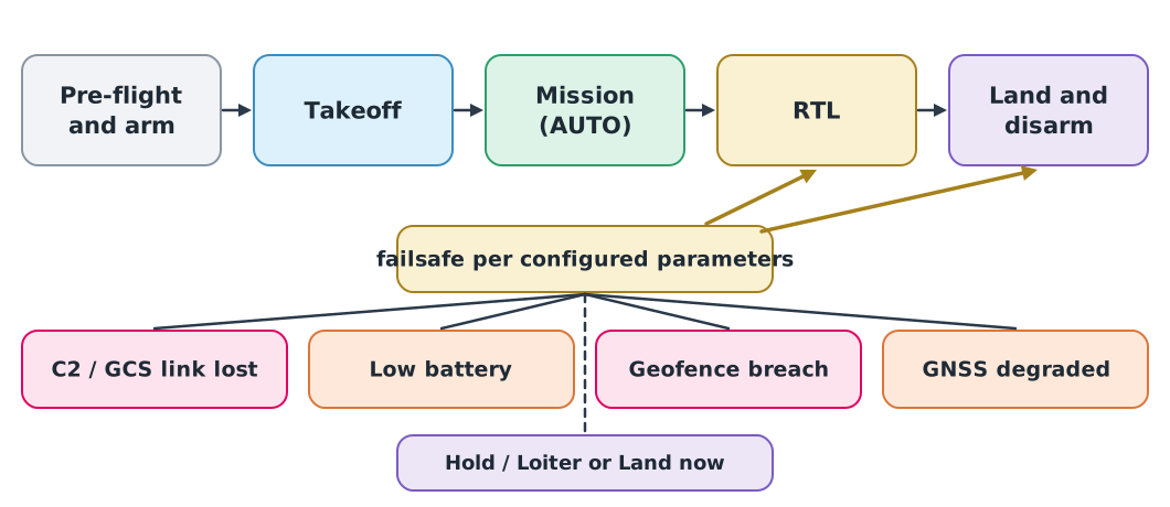
Mode names differ slightly: ArduPilot uses AUTO, GUIDED, LOITER, RTL and LAND, while PX4 uses Mission, Hold, Return and Land. The idea is the same: when a configured condition occurs, the autopilot changes mode by itself as configured.
Defaults you must know
This table was checked on 26 September 2026 against the PX4 parameter reference (main branch) and the ArduPilot Copter 4.6.3 source code. Values change between versions, so always check the documentation for the version you fly.
| Topic | PX4 | ArduPilot Copter |
|---|---|---|
| GCS link-loss failsafe | NAV_DLL_ACT = 0, disabled; timeout COM_DL_LOSS_T = 10 s | FS_GCS_ENABLE = 0, disabled; timeout FS_GCS_TIMEOUT = 5 s |
| RC loss failsafe | NAV_RCL_ACT = 2 (Return) after 0.5 s | Set with the FS_THR_* parameters |
| Low battery | Thresholds 15% / 7% / 5% (BAT_LOW_THR, BAT_CRIT_THR, BAT_EMERGEN_THR) | BATT_FS_LOW_ACT = 0, warn only |
| Geofence | GF_ACTION = 2 (Hold); horizontal and vertical limits = 0, i.e. off | FENCE_ENABLE = 0, off; when enabled, 300 m radius, 100 m ceiling, then RTL or Land |
| RTL altitude | RTL_RETURN_ALT = 60 m | RTL_ALT = 1500 cm (15 m); renamed RTL_ALT_M in 4.8 |
The key point is that the GCS link-loss failsafe is disabled by default in both systems. An automated mission without it will keep flying the mission after the station has lost sight of the aircraft. That may be what you want, or it may be dangerous, depending on the risk assessment.
Return-to-Launch (RTL)
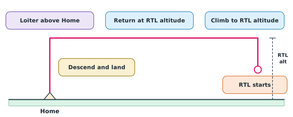
ArduPilot Copter RTL climbs to RTL_ALT if it is lower (if it is already higher it keeps its altitude), flies home, loiters above home for RTL_LOIT_TIME (default 5 s), then lands. PX4 Return climbs to RTL_RETURN_ALT, flies home, descends to RTL_DESCEND_ALT (30 m), then lands.
RTL is not always the safe answer. If the RTL altitude is below buildings or trees on the way back, or people have moved into the home area, RTL may be more dangerous than landing immediately. The choice must come from the site assessment in module 1.
Example 1 Energy to keep for RTL
The drone is 1.5 km from home at 60 m. Return airspeed is 10 m/s into a 3 m/s headwind; it descends at 2 m/s, loiters 5 s, draws 350 W on average, and the battery holds 177.6 Wh.
- Return leg s
- Descent s plus 5 s loiter, so s minutes
- Wh, or 13.6% of the battery
The low-battery threshold that triggers RTL from the farthest point must therefore be above 13.6% plus the reserve required at landing. Accepting PX4’s 15% default without thinking leaves very little margin if the wind is stronger than expected.
Geofence
A geofence is a virtual boundary the autopilot uses to detect that the aircraft has left its area. It can be a circle around home, a polygon, or an altitude ceiling. On a breach the configured action runs, such as Hold, RTL or Land.
The geofence must sit inside the edge of the authorised area, because the aircraft needs distance to stop. Stopping distance is the distance flown during the reaction time, , plus the braking distance .
Example 2 Geofence margin
Speed 12 m/s, reaction time 1 s, deceleration 3 m/s², GNSS error 3 m.
- m
- Adding position error: m
Place the geofence at least about 40 m inside the authorised boundary. With a tailwind blowing outward, braking distance is longer still. Real values must be confirmed by testing the aircraft type in use.
Test in SITL before flying
SITL (Software In The Loop) runs the real autopilot software on a computer, with a simulator generating motion and sensor data. Missions and failsafes can be tested without risking an aircraft. A recommended sequence:
- Choose ArduPilot or PX4 and pin the software version to the one you will fly
- Load the same parameter set as the aircraft
- Upload the mission, fly it completely and keep the log
- Inject one fault at a time, such as disconnecting the GCS, draining the simulated battery or flying into the geofence, and read the mode sequence from the log
- Compare behaviour with the plan, adjust, and test again
SITL shows that the logic and configuration behave as intended. It does not certify how the real aircraft behaves in real wind or with real radio links.
Monitoring during flight
During an automated mission the pilot still watches key values and compares them with the plan:
- Current mode and the waypoint being flown to
- Remaining energy against the energy needed to return (Example 1)
- GNSS quality and state-estimate health
- Link quality and the age of the latest telemetry
- Wind estimated from actual flight versus the forecast
Agree abort criteria before take-off, for example remaining energy below the calculated line, or wind above the limit in the aircraft manual, so that the team does not have to make new decisions under pressure.
Class activity
Activity: Simulated mission and RTL in SITL
Follow lab guide L01 and the ArduPilot SITL, QGroundControl or Mission Planner guides in the drone knowledge hub (instructor demonstration, or hands-on if computers are ready).
- Build a 6–8 waypoint mission in the simulated area; save the mission file and parameters.
- Calculate RTL energy from the farthest point and propose a low-battery threshold.
- Calculate the geofence margin and configure it in SITL.
- Simulate a GCS link loss with the failsafe disabled and enabled; compare the mode sequences in the logs.
Common mistakes
Watch out
- Assuming the drone will come home when the link is lost without checking that the failsafe is enabled
- Using the default RTL altitude where buildings or trees are taller
- Placing the geofence exactly on the authorised boundary with no stopping margin
- Mixing altitude references, height above home versus above mean sea level
- Testing in SITL with a different version or a different parameter set from the aircraft
Summary
- An automated mission is a list of MAVLink mission items such as TAKEOFF, WAYPOINT, RTL and LAND
- Failsafes change mode automatically; the GCS link-loss failsafe is disabled by default in both PX4 and ArduPilot
- The low-battery threshold must cover RTL energy from the farthest point plus the landing reserve
- The geofence must sit inside the authorised boundary by at least the stopping distance plus position error
- SITL tests logic and configuration but does not certify real-world behaviour
Check your understanding
- Which MAVLink command flies to a given position, and what is its ID?
- If the GCS link failsafe is not configured in ArduPilot Copter, what happens when the link is lost during an AUTO mission?
- At 10 m/s with a 1 s reaction time and 2.5 m/s² deceleration, what is the stopping distance?
- The drone is 1.2 km from home, returns at 12 m/s in calm air, descends 50 m at 2.5 m/s with no loiter, and draws 300 W. How much energy does RTL need?
- Why is RTL not always the safest option?
Answers
MAV_CMD_NAV_WAYPOINT, ID 16- The default
FS_GCS_ENABLE= 0 means there is no GCS link failsafe, so the drone continues the mission (unless another failsafe, such as RC or battery, triggers) - m
- s; energy Wh
- The return path may have obstacles above the RTL altitude, people may be at home, or energy may be insufficient. Landing immediately or at an alternate site can be safer
Key formulas
| RTL time | |
| RTL energy | |
| Stopping distance |
Key references
- PX4 Autopilot. PX4 user and developer guide. link
- ArduPilot Dev Team. ArduPilot documentation. link
- MAVLink Development Team. MAVLink developer guide. link
- ArduPilot Dev Team. SITL simulator (software in the loop). link
- Beard, R. W., & McLain, T. W. (2012). Small unmanned aircraft: Theory and practice. Princeton University Press.
- International Organization for Standardization. (2023). Unmanned aircraft systems – Part 3: Operational procedures (ISO 21384-3:2023). link
Further reading
Study the assigned knowledge units in advance, review media and take the module quiz
PX4 and ArduPilot architecture
Developing simulations and connecting SITL
Simulated missions and Return to Launch
ArduPilot SITL
QGroundControl
Mission Planner
In class / field
Lecture, case discussion and in-class problem solving
Learning evidence: Quiz results and submitted exercises