AC, RC and RL circuits
DRT 113 Fundamentals of Electrical and Electronics
Lesson
By the end of this module you will be able to
- Explain sinusoidal AC, peak value, RMS value, frequency and period
- Calculate charge, energy and the time constant of an RC circuit
- Explain an RC low-pass filter and calculate its cut-off frequency
- Explain induced voltage in an inductor and why voltage spikes occur in motor drive circuits
- Explain the roles of capacitors and inductors in a drone's electrical system
Electricity that changes with time
In Modules 1–2, voltage and current were constant. On a real drone, signals change all the time: ESCs switch motor current tens of thousands of times a second, chargers take AC mains, and sensors pick up high-frequency noise. Two components respond to these changes: the capacitor and the inductor. This module covers AC and these two components.
Alternating current
Alternating current (AC) changes direction and size back and forth as a sine wave:
where is the peak value and the frequency in hertz (cycles per second). The period is the time for one cycle, .
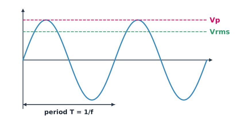
Because the value keeps changing, we state its size as the RMS value: the DC value that would produce the same heating in a resistor. For a sine wave
Example 1. Thai mains
Thailand’s low-voltage supply is specified at 230 V, 50 Hz (often called 220 V). The 230 V is the RMS value.
- Peak V
- Period s, or 20 ms
Equipment on mains must therefore withstand a peak well above the label value. Mains is lethal: never open a charger or power supply while it is plugged in.
Capacitors
A capacitor stores charge on two conducting plates separated by an insulator. The charge is proportional to voltage:
where is capacitance in farads (F); practical values are usually microfarads (µF) or nanofarads (nF).
Example 2. A capacitor at the ESC power input
A 1000 µF capacitor at 25 V:
- Charge C
- Energy J
That is tiny compared with the battery, but it can be released very fast. It supplies brief current bursts when the ESC switches and absorbs voltage spikes caused by long leads, which is why many ESC makers recommend a low-ESR capacitor close to the power terminals.
RC circuits and the time constant
When a capacitor is connected to a supply through a resistor, its voltage does not jump instantly; it rises exponentially:
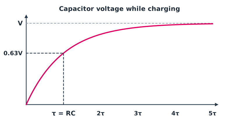
is the time constant. After the voltage reaches about 63% of its final value; after it is over 99%, and in practice considered fully charged.
The low-pass filter
A capacitor passes high frequencies more easily than low ones. Its frequency-dependent opposition, reactance , falls as frequency rises. A resistor in series with the output taken across the capacitor makes a low-pass filter with cut-off frequency
Example 3. Filtering sensor noise
With kΩ and nF:
Signals much slower than this, such as slowly changing battery voltage, pass almost unchanged, while ESC switching noise at tens of kilohertz is strongly reduced.
Inductors
An inductor is a coil of wire. When its current changes, the magnetic field in the coil changes and induces a voltage that opposes the change:
where is inductance in henries (H). An inductor behaves like “inertia” for current: it resists sudden change. Its reactance rises with frequency, the opposite of a capacitor.
Example 4. Why voltage spikes happen
A motor winding or long lead has about 50 µH of inductance. If the ESC cuts 10 A in 1 µs:
This brief spike is many times the battery voltage and can destroy MOSFETs. Real ESCs include diodes and capacitors to absorb the energy, and battery-to-ESC leads should be kept as short as possible.
On a drone, inductors appear in BLDC motor windings, switching regulators (such as buck BECs) and video-system noise filters.
Module lab
In class
- View a function-generator signal on an oscilloscope. Read peak, period and frequency, and compare with the RMS value on a multimeter.
- Build an RC circuit with kΩ and µF. Apply a slow square wave, measure the time to reach 63% and compare with s.
- Feed sine waves of different frequencies into an RC filter, record output amplitude and find where it drops to about 70.7%.
Safety. Electrolytic capacitors are polarised and can burst if reversed; use a voltage rating above the working voltage.
Common mistakes
Watch out
- Confusing peak with RMS. 230 V mains peaks at about 325 V.
- Forgetting to convert µF and nF before calculating.
- Reversing an electrolytic capacitor or using too low a voltage rating.
- Ignoring the inductance of long leads, which causes spikes when current changes fast.
Summary
- Sinusoidal AC is described by peak, RMS (), frequency and period; Thai mains is 230 V, 50 Hz.
- A capacitor stores and energy ; an RC circuit has time constant and filters at .
- An inductor, , resists changes in current and causes spikes when current is cut quickly.
- On drones, capacitors steady the ESC supply and filter noise; inductors are in motors and power converters.
Check your understanding
- What is the RMS value of a sine wave with a 17 V peak?
- What is the period of a 400 Hz signal in milliseconds?
- What is the time constant of an RC circuit with kΩ and µF?
- For a low-pass cut-off near 160 Hz with µF, what is needed?
- If frequency doubles, how does an inductor’s reactance change?
Answers
- V
- s, or 2.5 ms
- s
- , so about 1 kΩ
- It doubles, since
Key formulas
| Sinusoidal voltage | |
| RMS value | |
| Period | |
| Capacitor | |
| RC charging | |
| RC cut-off frequency | |
| Inductor | |
| Reactance |
Key references
- Ling, S. J., Sanny, J., & Moebs, W. (2016). University physics volume 2. OpenStax. link
- Boylestad, R. L., & Nashelsky, L. (2013). Electronic devices and circuit theory (11th ed.). Pearson.
- Horowitz, P., & Hill, W. (2015). The art of electronics (3rd ed.). Cambridge University Press.
Further reading
Study the assigned knowledge units in advance, review media and take the module quiz
In class / field
Lab or field practice from worksheets with a safety checklist
Learning evidence: Checked worksheets and quiz results