Semiconductors, transistors and PWM
DRT 113 Fundamentals of Electrical and Electronics
Lesson
By the end of this module you will be able to
- Explain diodes and LEDs and calculate forward-voltage losses
- Explain the MOSFET as an electronic switch and calculate Rds(on) losses
- Explain pulse-width modulation (PWM) and calculate average voltage from duty cycle
- Explain PWM and DShot ESC control signals and the ESC's role in driving a BLDC motor
- Compare linear and switching voltage regulators (BECs)
The parts that make electricity “smart”
Resistors, capacitors and inductors behave in fixed ways. But a drone must adjust motor speed hundreds of times per second. What makes that possible are semiconductor devices that switch current on and off under control. This module covers diodes, MOSFETs and PWM, the heart of every ESC and power system on a drone.
Diodes and LEDs
A diode lets current flow one way. When forward-biased (positive at the anode) it conducts with a roughly constant voltage across it, the forward voltage : about 0.7 V for silicon and 0.3–0.4 V for a Schottky diode. Reverse-biased, it barely conducts.
An LED is a diode that emits light. Its is higher (about 1.8–3.3 V depending on colour) and it always needs a current-limiting resistor, as calculated in Module 1.
Example 1. A reverse-polarity diode
A Schottky diode in series with the main lead to guard against reversed battery connection, at 30 A with V:
12 W of heat in a small part is far too much. High-current circuits therefore use a MOSFET acting as an “ideal diode”, or polarised connectors that cannot be plugged in backwards.
Transistors and MOSFETs
A transistor is a switch or amplifier controlled by a small signal. Drone power circuits mostly use MOSFETs, because they are controlled by voltage at the gate, need almost no gate current and switch very fast.
With enough gate voltage, a MOSFET turns on with a very low drain–source resistance, . With low gate voltage it turns off and almost no current flows. Its conduction loss is
Example 2. Heat in an ESC MOSFET
A MOSFET with mΩ carries 30 A:
ESCs therefore need heat sinks or mounting where propeller airflow can cool them. There are also switching losses, which rise with switching frequency.
Pulse-width modulation (PWM)
To give a motor “half” voltage, there is no need to burn energy in a resistor. Instead, switch fully on for half the time and fully off for the other half, very quickly. This is PWM, and the fraction of time on is the duty cycle:
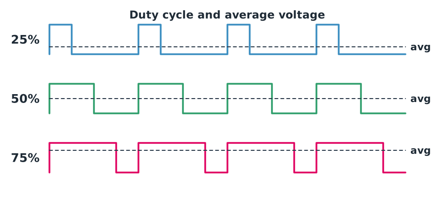
Because a switch that is fully on or fully off wastes almost no energy, PWM is highly efficient. The motor windings, being inductors (Module 3), smooth the current naturally.
Example 3. Average voltage
A fully charged 4S battery at 16.8 V with 25% duty cycle gives an average of V.
The ESC and control signals
An ESC (Electronic Speed Controller) takes speed commands from the flight controller and switches six MOSFETs in three pairs to feed current into the three phases of a BLDC motor in sequence, creating a rotating magnetic field.
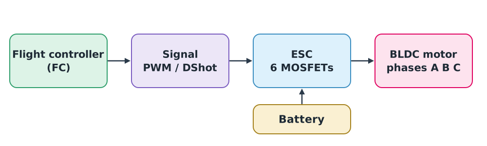
Two command signals are common:
- Servo-style PWM sends pulses 1000–2000 µs wide, repeated tens to hundreds of times per second. 1000 µs means zero throttle and 2000 µs full. ESCs using it must be calibrated to the pulse range.
- DShot is a digital protocol that sends speed as a number with a checksum. It needs no calibration and resists noise better. It comes in several speeds such as DShot150, DShot300 and DShot600; ArduPilot’s documentation recommends DShot150 for larger aircraft with long signal leads, as the most noise-tolerant.
Example 4. Reading throttle from a pulse
A 1350 µs pulse corresponds to
Voltage regulators and BECs
The flight controller, radios and camera need a steady 5 V or 12 V, but the battery gives 14.8–25.2 V, so a step-down regulator is needed, called a BEC (Battery Eliminator Circuit). There are two main types:
- Linear regulators drop the excess voltage as heat: .
- Switching (buck) regulators use a MOSFET with an inductor and capacitor, often reaching about 85–95% efficiency.
Example 5. Comparing losses
Stepping 22.2 V down to 5 V at 1 A:
- Linear: loss W, over three times the 5 W the load actually uses
- Switching at 90% efficiency: input W, loss only about 0.56 W
High-voltage drones therefore almost always use switching BECs, but their switching noise must be kept away from video and radio systems.
Module lab
In class
- Measure the forward voltage of silicon and Schottky diodes and LEDs of several colours with a multimeter’s diode mode.
- Use a microcontroller to generate PWM driving a MOSFET and a small DC motor. Measure duty cycle on an oscilloscope and average voltage on a multimeter.
- Connect a servo tester to an ESC with propellers removed and view the 1000–2000 µs pulses on the oscilloscope.
Safety. Always remove propellers when testing ESCs on the bench, and use a smoke stopper at first power-up.
Common mistakes
Watch out
- Using an ordinary diode in a high-current path, causing heat and waste.
- Driving a MOSFET gate with too little voltage. It only partly turns on; is high and it runs very hot.
- Using servo PWM without calibrating the ESCs. Motors may spin unevenly or not start.
- Using a linear regulator across a large voltage difference. It gets very hot.
Summary
- A diode conducts one way with a forward voltage , losing .
- A MOSFET is a voltage-controlled switch with conduction loss .
- PWM sets the average voltage efficiently.
- An ESC switches six MOSFETs to drive a three-phase motor, commanded by 1000–2000 µs PWM or digital DShot.
- Switching BECs are far more efficient than linear regulators for large voltage drops.
Check your understanding
- A silicon diode with V carries 2 A. What power does it lose?
- How many watts does a 3 mΩ MOSFET dissipate at 40 A?
- A PWM period is 50 µs and on-time 20 µs. What is the duty cycle?
- What throttle percentage does an 1800 µs pulse represent?
- A linear regulator drops 12 V to 5 V at 0.5 A. How much power does it lose?
Answers
- W
- W
- , or 40%
- W
Key formulas
| Diode loss | |
| MOSFET conduction loss | |
| Duty cycle | |
| PWM average voltage | |
| Throttle from pulse width | |
| Linear regulator loss |
Key references
- Boylestad, R. L., & Nashelsky, L. (2013). Electronic devices and circuit theory (11th ed.). Pearson.
- Horowitz, P., & Hill, W. (2015). The art of electronics (3rd ed.). Cambridge University Press.
- ArduPilot Dev Team. ESCs and motors; DShot ESCs. link
- Ling, S. J., Sanny, J., & Moebs, W. (2016). University physics volume 2. OpenStax. link
Further reading
Study the assigned knowledge units in advance, review media and take the module quiz
In class / field
Lab or field practice from worksheets with a safety checklist
Learning evidence: Checked worksheets and quiz results