Automation
DRT 344 Automation, Robotics and Intelligent Control Systems
Lesson
By the end of this module you will be able to
- Explain the elements of an automation system from sensors and controllers to actuators
- Place devices and software in the ISA-95 hierarchy
- Explain the PLC scan cycle and the IEC 61131-3 programming languages
- Calculate worst-case response time from the scan cycle and the bandwidth of IoT data
- Compare MQTT and OPC UA for connecting drones to automation systems
Why this matters
Modern drones do not work alone. A warehouse inventory drone must talk to the warehouse management system; an automated docking station (drone-in-a-box) must open its lid, charge the battery and report status to a control centre. People working with UAS and automation need to understand the language of industry: PLCs, sensors, actuators and communication protocols.
An automation system is like a human body. Sensors are the senses, the controller is the brain, actuators are the muscles, and the network is the nerves carrying signals between them.
Elements of an automation system
| Element | Role | Example in drone work |
|---|---|---|
| Sensor | Measures the real state and converts it to a signal | Dock lid switch, battery temperature sensor, camera |
| Controller | Decides according to a program or control law | The dock’s PLC, the flight controller’s microcontroller |
| Actuator | Turns commands into physical action | Lid motor, charging relay, propeller motors |
| Embedded system | A small computer built into a device for a dedicated task | Flight controller board, onboard image-processing computer |
| Communication | Carries data between devices and systems | Factory fieldbus, MQTT to the cloud |
The term Industrie 4.0 was introduced publicly at Hannover Messe in April 2011 to describe connecting machines, data and the internet. That is the context in which drones and robots become part of automation systems.
The ISA-95 hierarchy
ISA-95 (also IEC 62264) divides enterprise automation into levels. It shows where each device and data stream sits and what it must connect to.
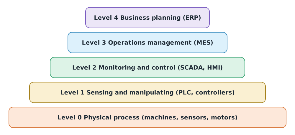
Example placement for a warehouse inventory drone: the drone and barcode reader sit at levels 0–1; mission software and status screens at level 2; the warehouse management system at level 3; and the ERP that uses stock counts to plan purchasing at level 4.
PLCs and the scan cycle
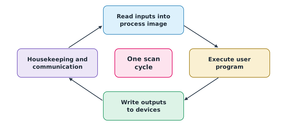
A PLC (programmable logic controller) is an industrial computer built to survive factory conditions and repeat its work predictably. It runs in an endless cycle. The Siemens S7-1200 manual describes each cycle as writing the outputs, reading the inputs, executing the user program and performing background tasks, using a process image, a memory copy of I/O states, so the program sees constant input values throughout one cycle.
IEC 61131-3 programming languages
IEC 61131-3 Edition 4 (2025) defines the PLC languages:
- Ladder Diagram (LD), a graphical language that mimics relay circuits, suited to electricians
- Function Block Diagram (FBD), which wires function blocks together
- Structured Text (ST), a textual language like general-purpose programming languages, suited to calculation
- Sequential Function Chart (SFC), used to organise process sequences
Instruction List (IL), formerly part of the standard, was removed in Edition 4, although some vendors still support it.
Example 1 Start/stop logic for a drone dock lid
The most common ladder pattern is the seal-in circuit, written in ST as:
Motor := (Start OR Motor) AND NOT Stop AND NOT Fault;
- Pressing Start runs the motor, which latches itself (OR Motor) after the button is released
- Pressing Stop, or a Fault signal such as a sensor detecting a hand in the lid gap, stops the motor at once
- Wiring Stop and Fault as AND NOT gives stopping priority over running, a basic safety principle
Response time from the scan cycle
If an input changes just after the PLC has read its inputs, the change is seen only in the next cycle, and the output is written later still. The worst-case response is roughly:
Example 2 A conveyor feeding boxes to a delivery drone
The PLC scan time is 10 ms, input and output delays total 4 ms, and the conveyor moves at 0.5 m/s.
- ms
- In that time a box moves m, or 12 mm
If the pick-up point must be more accurate than 12 mm, reduce the scan time, use an interrupt input, or slow the conveyor before the pick-up point.
IoT and communication protocols
MQTT is a lightweight publish/subscribe protocol through a broker, suited to many devices and bandwidth-limited networks (see the deep-dive knowledge unit on MQTT and Eclipse Mosquitto). The OASIS MQTT 5.0 standard (2019) defines three delivery levels:
| QoS | Meaning in the standard | Suited to |
|---|---|---|
| 0 | At most once; messages may be lost | Frequent telemetry where new data replaces old |
| 1 | At least once; arrives but may be duplicated | Events that must not be lost, where duplicates can be handled |
| 2 | Exactly once | Commands that must not repeat, such as deducting stock |
OPC UA (IEC 62541) is an industrial data-exchange standard with a built-in information model and security, commonly used between machines and level 2–3 systems. MQTT is common for sending data to the cloud and between large numbers of IoT devices.
Example 3 Telemetry bandwidth for a drone fleet
Ten drones each send 200-byte telemetry messages 5 times per second over MQTT.
byte/s kbit/s
This excludes protocol headers and TLS encryption, which increase the real size. If a remote link supports less, reduce the rate or compress the data.
Class activity
Activity: Designing the logic of an automated drone dock
- List the sensors and actuators of a dock that opens its lid, receives a landing drone and charges its battery.
- Write ST or ladder logic for the lid-opening step that stops immediately on any hazard signal.
- Place every device and software component in the ISA-95 hierarchy.
- Choose MQTT QoS levels for telemetry, battery status and a drone-release command, with reasons.
Common mistakes
Watch out
- Assuming a PLC responds instantly, ignoring the scan cycle
- Giving the run command priority over stop in the logic
- Using QoS 2 for every message, slowing the network needlessly
- Sending MQTT without encryption or authentication in systems that command real equipment
- Claiming IL is a current standard language when the 2025 edition removed it
Summary
- Automation systems consist of sensors, controllers, actuators, embedded systems and communication
- ISA-95 defines levels 0–4 from the physical process to business planning
- A PLC runs a scan cycle through a process image; worst-case response is about
- IEC 61131-3:2025 defines LD, FBD, ST and SFC
- MQTT has QoS 0, 1 and 2; OPC UA suits industrial machine connectivity
Check your understanding
- At which ISA-95 level are SCADA and HMI?
- Why does a PLC read inputs into a process image before executing the program?
- With a 20 ms scan time and 5 ms I/O delay, what is the approximate worst-case response?
- Four drones send 250-byte messages at 10 Hz. What bandwidth is needed in kbit/s (excluding headers)?
- Which QoS suits frequent position telemetry, and why?
Answers
- Level 2 (monitoring and control)
- So the program sees constant input values throughout one cycle, not values changing mid-execution
- ms
- byte/s kbit/s
- QoS 0, because new messages quickly replace old ones, losing one does no harm, and it reduces network load
Key formulas
| PLC worst-case response (approx.) | |
| Data bandwidth |
Key references
- Groover, M. P. (2019). Automation, production systems, and computer-integrated manufacturing (5th ed.). Pearson.
- Bolton, W. (2015). Programmable logic controllers (6th ed.). Newnes.
- International Electrotechnical Commission. (2025). Programmable controllers – Part 3: Programming languages (IEC 61131-3:2025, Ed. 4.0). link
- Siemens AG. (2009). SIMATIC S7-1200 getting started (A5E02486791-01). link
- International Society of Automation. ISA-95 standard: Enterprise-control system integration (ANSI/ISA-95, IEC 62264). link
- International Electrotechnical Commission. (2025). OPC unified architecture – Part 1: Overview and concepts (IEC 62541-1:2025). link
- OASIS. (2019). MQTT version 5.0 (OASIS Standard, 7 March 2019). link
- Wahlster, W. (2021). Ten years of INDUSTRIE 4.0 [Interview]. DFKI. link
Further reading
Study the assigned knowledge units in advance, review media and take the module quiz
Industrial automation and PLCs
Deep dive: MQTT and Eclipse Mosquitto for drone and IoT systems
In class / field
Lecture, case discussion and in-class problem solving
Learning evidence: Quiz results and submitted exercises