Payloads and integration
DRT 341 Advanced Unmanned Aircraft Systems Technology and System Architecture
Lesson
By the end of this module you will be able to
- Choose a payload type from the mission question
- Identify the four interfaces of payload integration: mechanical, electrical, data and timing
- Build a power budget and assess a payload's effect on endurance
- Calculate data volumes and position errors from poor time synchronisation
- Use a weighted decision matrix to compare COTS and custom systems
The payload is why the drone flies
Users do not buy drones because they want them to fly, but for the data or service the payload provides: map imagery, thermal images of solar panels, delivery of medical supplies. The aircraft is just the payload’s vehicle. Poor payload choice or integration can fail a mission even when the aircraft flies perfectly.
Choose the payload from the mission question
Drone-Hub offers a sound principle: start from the question you need to answer, not the camera you have.
| Mission question | Possible payload | What to check |
|---|---|---|
| Shape and visible condition | RGB camera | Resolution, lens, light, overlap |
| Plant health or spectral reflectance | Multispectral camera | Radiometric calibration and band alignment |
| Temperature or abnormal hot spots | Radiometric thermal camera | Emissivity and measurement conditions |
| 3D shape under trees | LiDAR | Alignment with IMU/GNSS and timing |
| Delivery | Release mechanism or winch | Drop-zone safety and centre-of-gravity effects |
| Extending communications | Radio relay | Interference with your own C2 link |
Four interfaces
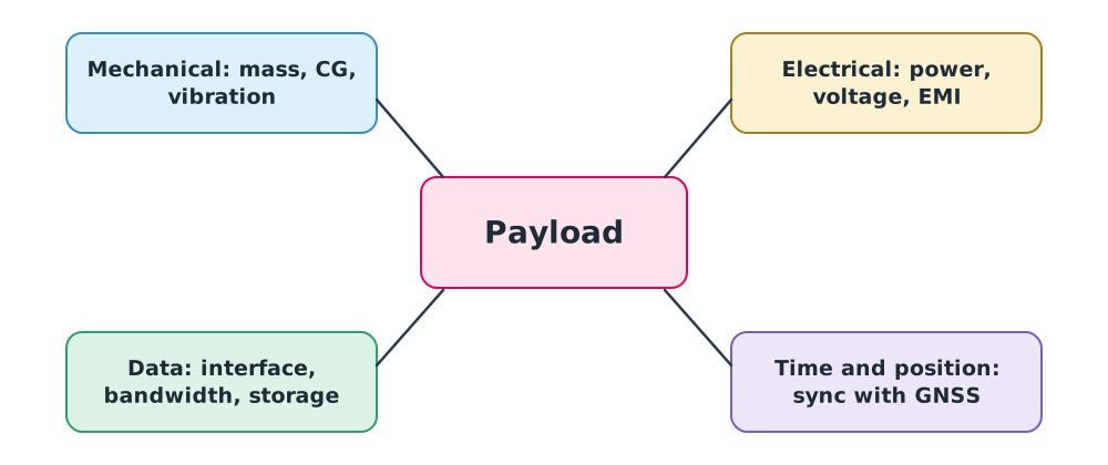
- Mechanical: mass and centre of gravity (see DRT 112), mounting, isolation from motor vibration, clearance from propellers.
- Electrical: voltage, current, total power, and electromagnetic interference (EMI) with compass, GNSS and radios.
- Data: interface (USB, Ethernet, HDMI, UART, etc.), data rate, storage and downlink.
- Time and position: every image or data point must know when and where it was taken, so timing must be synchronised with GNSS.
Power budget
Example 1. How much flight time does a payload cost?
A multirotor uses 237 W for propulsion and carries a 3 W flight controller, 1 W telemetry radio, 10 W camera, 5 W gimbal and 10 W onboard computer.
- Equipment total 29 W, overall 266 W
- Endurance falls to , about 11% less from electrical load alone
- This excludes the equipment’s weight, which raises propulsion power as (DRT 112 Module 4)
Data volume
Example 2. How much storage?
Recording video at 20 Mbps for 30 minutes:
To stream this live, the payload link must sustain at least 20 Mbps, hundreds of times what a typical C2 link carries.
Time synchronisation
Example 3. Wrong time, wrong position
A survey drone flies at 15 m/s. If the time stamped on an image is 0.1 s off true GNSS time, the image position is wrong by
For centimetre-level mapping this is unacceptable. Professional systems use the GNSS PPS signal or the camera hot shoe to record exact capture times.
COTS or custom
COTS (commercial off-the-shelf) systems are ready to use, well tested and supported, but may be hard to customise, partly closed, or tied to a single vendor. Custom systems fit the mission but carry the burden of testing, certification and maintenance.
A systematic choice uses a weighted decision matrix:
Example 4. Choosing an inspection system
Score each option 1–5 per criterion, with weights agreed by the team.
| Criterion | Weight | A: Full COTS | B: COTS + other payload | C: Custom |
|---|---|---|---|---|
| Mission performance | 0.35 | 3 | 4 | 5 |
| SWaP | 0.25 | 5 | 4 | 3 |
| Lifecycle cost | 0.20 | 4 | 3 | 2 |
| Support and spares | 0.20 | 5 | 3 | 2 |
| Total | 4.10 | 3.60 | 3.30 |
Option A scores highest under these weights. If the organisation weighted performance much more heavily, the result might change, so test different weights (sensitivity analysis) and always record why the weights were chosen.
Class activity
Case study
- Build power and mass budgets for an example drone with two different payloads and estimate the change in endurance.
- Draft a one-page Interface Control Document for mounting a thermal camera on the lab drone.
- Build a decision matrix for a mission in your organisation and test how far the weights can change before the result flips.
Common mistakes
Watch out
- Choosing a payload by top specification rather than the mission question.
- Ignoring the payload’s power budget and its weight effect on endurance.
- Not synchronising time, giving mispositioned data.
- Setting matrix weights after seeing the scores, biasing the result.
Summary
- Choose the payload from the question the mission must answer.
- Integration has four interfaces: mechanical, electrical, data, and time with position.
- Payload power and weight both cut endurance.
- Data size = bitrate × time / 8; timing position error = speed × time error.
- A weighted decision matrix compares COTS and custom options transparently.
Check your understanding
- Which payload suits locating hot spots on solar panels?
- Equipment draws 40 W on a drone using 300 W for propulsion. By what percentage does endurance fall from electrical load alone?
- How many GB is one hour of 8 Mbps video?
- At 10 m/s with a 50 ms timing error, what is the position error?
- With weights 0.5, 0.3, 0.2 and scores 4, 2, 5, what is the total?
Answers
- A radiometric thermal camera
- , about 12% less
- bytes ≈ 3.6 GB
- m
Key formulas
| Power budget | |
| Video data size | |
| Position error from timing | |
| Weighted score |
Key references
- Fahlstrom, P. G., Gleason, T. J., & Sadraey, M. H. (2022). Introduction to UAV systems (5th ed.). Wiley.
- INCOSE. (2023). INCOSE systems engineering handbook (5th ed.). Wiley.
- Austin, R. (2010). Unmanned aircraft systems: UAVS design, development and deployment. Wiley.
- Wolf, P. R., Dewitt, B. A., & Wilkinson, B. E. (2014). Elements of photogrammetry with applications in GIS (4th ed.). McGraw-Hill.
Further reading
Study the assigned knowledge units in advance, review media and take the module quiz
Payloads and survey data quality
Designing and integrating drone systems
In class / field
Lecture, case discussion and in-class problem solving
Learning evidence: Quiz results and submitted exercises