Control, navigation and communication
DRT 341 Advanced Unmanned Aircraft Systems Technology and System Architecture
Lesson
By the end of this module you will be able to
- Explain autopilot software architecture from sensors to motor commands
- Compare navigation sources GNSS, RTK, IMU, barometer, magnetometer and visual navigation
- Explain the C2 link as defined by ICAO and the other links in a UAS
- Calculate free-space path loss and a simple link margin
- Assess the readiness of control, navigation and communication before a mission
The drone’s brain and nervous system
If the power system is the muscle, control, navigation and communication are the brain and nerves. The drone must know where it is, which way it faces, where it must go, and keep people on the ground informed. Failures here are often the most dangerous: a drone that can still fly but does not know where it is may wander far from safe areas.
Autopilot architecture
Widely used open-source autopilots such as PX4 and ArduPilot share a similar structure.
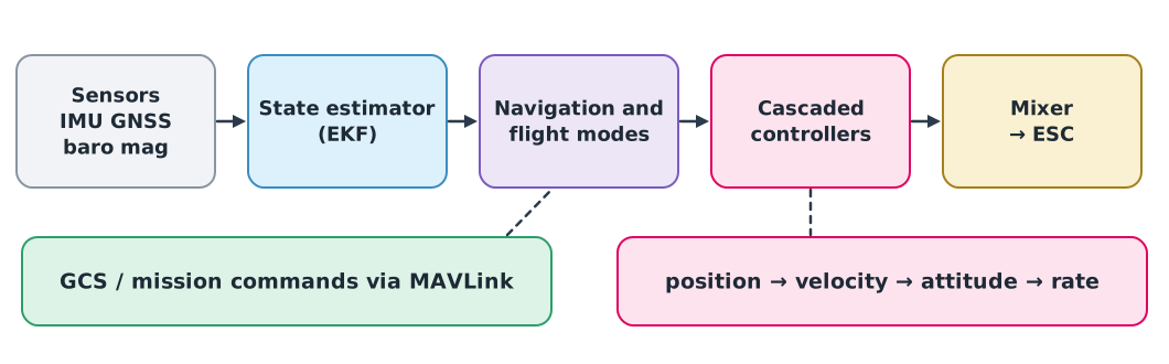
- Sensors provide noisy raw data.
- State estimation uses an extended Kalman filter (EKF) to fuse several sensors into best estimates of position, velocity and attitude, with uncertainty.
- Navigation and flight modes turn a mission or pilot command into targets, such as the next waypoint or return to launch.
- Cascaded controllers: the outer loop controls position and passes a velocity target inward, then attitude and rotation rate. The innermost loop runs fastest.
- The mixer turns force and moment commands into individual motor commands for the ESCs.
PX4 is built from modules communicating through an internal messaging system, making modules easy to replace or add. ArduPilot has a long history and supports many vehicle types. Both use the MAVLink protocol to talk to ground stations. Tuning is covered in DRT 347 and 348.
Navigation sources
| Source | Provides | Typical accuracy | Weakness |
|---|---|---|---|
| GNSS | Position, velocity | Metres | Can be blocked, jammed or spoofed |
| GNSS RTK | Position | Centimetres | Needs a base station or correction service and data link |
| IMU | Acceleration, rotation rate | Good short-term | Error accumulates over time |
| Barometer | Relative height | Decimetres to metres | Varies with weather and prop wash |
| Magnetometer | Heading | Degrees | Disturbed by metal and electric currents |
| Visual navigation / optical flow | Relative motion | Depends on surface and light | Needs texture on the ground and enough light |
No sensor is perfect. Fusing several with an EKF lets each cover the others’ weaknesses: the IMU gives fast, continuous data while GNSS corrects its accumulated drift (see DRT 111 Module 5).
Communication links
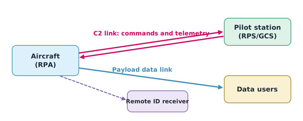
ICAO Annex 10 Volume VI defines the C2 link as the data link between aircraft and remote pilot station for managing the flight. A UAS also has:
- a payload data link for imagery or mission data, often needing far more bandwidth than C2;
- Remote ID, broadcasting identification and position to ground observers;
- in some systems, an RC link for manual piloting.
Link technologies range from 2.4 GHz and 900 MHz line-of-sight radios to 4G/5G cellular networks and satellite, which open the way to beyond-visual-line-of-sight flight (DRT 342).
Estimating link range
Radio signals weaken with distance and frequency. In open space with no obstruction, the loss is
Received power is (dBm and dB), and the margin is minus receiver sensitivity.
Example 1. A 2.4 GHz link at 2 km
Transmitter 20 dBm, 2 dBi antennas at both ends, receiver sensitivity −100 dBm.
- dB
- dBm
- Margin dB
An 18 dB margin is reasonable in the open, but trees, buildings, rain and antenna orientation can remove several more dB. Designers typically want at least about 10 dB after other losses. The communications course covers this in depth.
When the link drops
Link loss is a normal event to plan for. Autopilots offer configurable failsafes such as return to launch (RTL), land immediately or continue the mission. The choice must follow the area’s risk assessment, not the default every time, and must be tested in SITL before real flight.
Class activity
Case study
- Run PX4 or ArduPilot SITL, view the MAVLink messages leaving the aircraft and identify which stage of Figure 1 each comes from.
- Calculate the margin of a 900 MHz link at 5 km with values your instructor gives, then compare with 2.4 GHz.
- Analyse a GNSS-interference incident from the news or a report: which navigation sources could help, and for how long?
Common mistakes
Watch out
- Trusting GNSS unconditionally. Check satellite count, accuracy estimates and interference.
- Calibrating the compass near metal or vehicles.
- Leaving failsafes at defaults without assessing the area.
- Applying open-field link calculations to cluttered areas.
Summary
- An autopilot comprises sensors, state estimation (EKF), navigation and modes, cascaded controllers and a mixer.
- Each navigation source has weaknesses; fusion compensates.
- ICAO’s C2 link joins aircraft and remote pilot station for managing the flight, separate from payload and Remote ID links.
- FSPL and margin estimate link range; failsafes must follow the risk assessment.
Check your understanding
- Which loop in the cascaded structure runs fastest?
- Why can an IMU alone navigate only briefly?
- Calculate FSPL at 5 km and 900 MHz.
- If distance doubles, by how many dB does FSPL increase?
- What travels on the C2 link, and what on the payload link?
Answers
- The rate loop, the innermost
- Bias errors accumulate and grow with the square of time when integrated to position
- dB
- dB
- C2: flight commands and status telemetry. Payload link: images, video or mission sensor data
Key formulas
| Free-space path loss | |
| Received power | |
| Link margin |
Key references
- International Civil Aviation Organization. (2021). Annex 10 to the Convention on International Civil Aviation: Aeronautical telecommunications, Volume VI: Communication procedures relating to remotely piloted aircraft systems C2 link (1st ed.).
- PX4 Autopilot. PX4 user and developer guide. link
- ArduPilot Dev Team. ArduPilot documentation. link
- Groves, P. D. (2013). Principles of GNSS, inertial, and multisensor integrated navigation systems (2nd ed.). Artech House.
- Beard, R. W., & McLain, T. W. (2012). Small unmanned aircraft: Theory and practice. Princeton University Press.
- MAVLink Development Team. MAVLink developer guide. link
Further reading
Study the assigned knowledge units in advance, review media and take the module quiz
In class / field
Lecture, case discussion and in-class problem solving
Learning evidence: Quiz results and submitted exercises