UAS system architecture
DRT 341 Advanced Unmanned Aircraft Systems Technology and System Architecture
Lesson
By the end of this module you will be able to
- Explain the ICAO definitions of UAS and RPAS and their main elements
- Break a UAS down into air segment, ground segment, communication links, and people and procedures
- Explain the systems-engineering V model and the roles of requirements and testing
- Identify interfaces between subsystems and apply SWaP-C thinking to technology choices
- Calculate the reliability of series systems and systems with redundancy
See the drone as a “system”, not just an aircraft
When a drone crashes on a mission, people first ask “what broke on the aircraft?” Often the cause is not in the aircraft at all: a lost link, a wrong setting at the ground station, a battery not charged to procedure, or a team with different understandings of the mission. Professionals therefore view a drone as a system of parts working together.
This is the first core course of the continuing programme. Most students already know drone components. The first module moves from knowing components to reading and designing the architecture of the whole system.
UAS and RPAS in international terms
An unmanned aircraft (UA) has no pilot on board. An unmanned aircraft system (UAS) is the aircraft plus everything needed to fly it.
The International Civil Aviation Organization (ICAO) uses RPAS (remotely piloted aircraft system) for systems piloted from a remote location, defined as:
- RPA: the aircraft piloted from a remote pilot station
- RPS (remote pilot station): the station containing the equipment used to pilot the aircraft
- C2 link: the data link between aircraft and remote pilot station for managing the flight
- Other components as specified in the system’s type design
All RPAS are UAS, but a fully autonomous UAS with no pilot controlling it in flight is not an RPAS. The distinction matters legally, because most current regulations, including Thailand’s, still require a responsible person for every flight.
The four parts of a UAS
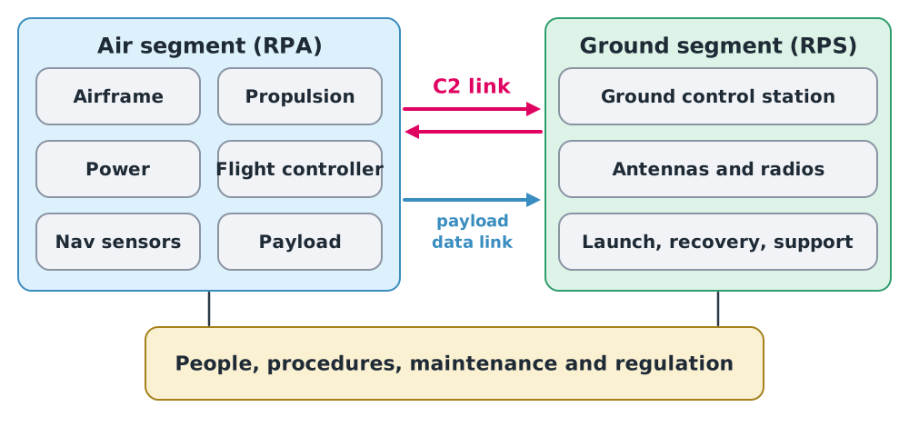
| Part | Main subsystems | Design question |
|---|---|---|
| Air segment | Airframe, propulsion, power, flight controller, navigation sensors, payload | Can it fly long and far enough? Can it carry the payload? |
| Ground segment | Ground control station, antennas and radios, launch/recovery and support | Does it work in the field? How long does set-up take? |
| Links | C2 link, payload data link, identification broadcast | Does it cover the area? What happens if it drops? |
| People and procedures | Pilots, observers, maintainers, manuals, licences | Who decides when something goes wrong? |
Key idea
System performance is limited by its weakest part. A drone with two hours’ endurance is useless if the C2 link covers only 20 minutes of the route, or if set-up takes so long the team misses the operating window.
Systems engineering and the V model
Systems engineering starts from mission needs, breaks them into system and subsystem requirements, then builds and tests back up level by level. The model most used to describe this is the V model.
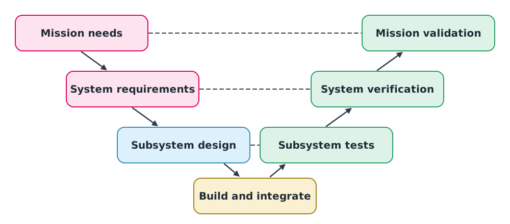
The left of the V defines what is needed; the right proves it was achieved. The dashed lines show that each test level checks against requirements at the same level.
- Verification asks “did we build it right, to the requirements?”
- Validation asks “did we build the right thing for the mission?”
Example 1. From mission to requirements
Mission: survey flood damage over 5 km² at 5 cm/pixel within 3 hours of notification.
Measurable requirements might include:
- Air segment: at least 60 minutes per flight, tolerating 10 m/s wind
- Payload: a camera giving 5 cm GSD at a legal flight height
- Ground: ready to fly within 15 minutes of arrival
- Links: coverage to a 3 km radius from take-off
Good requirements must be measurable and testable. “Long endurance” or “easy to use” are not yet requirements.
Interfaces and SWaP-C
Most integration problems occur at interfaces, where subsystems meet: power connectors, data formats, mounting points, timing. Development teams therefore write an Interface Control Document (ICD) stating what each side must provide and accept.
Technology selection for aircraft uses SWaP-C: Size, Weight, Power and Cost. The best camera on the market may be the wrong choice if its weight halves the flight time.
System reliability
Reliability () is the probability that a system or part performs as required for a period, such as one mission.
Series
If the system needs every part to work, reliability is the product:
Multiplying numbers below 1 keeps shrinking the result, so systems with many critical parts are more likely to fail.
Parallel (redundancy)
If parts are duplicated and the system still works while any one survives:
Example 2. The effect of redundancy
Per-mission reliability (illustrative values): flight controller 0.999, GNSS 0.995, C2 link 0.99, and four ESCs at 0.998 each, all essential.
That is about a 2.4% chance of a fault per mission, roughly one in every 40 missions.
- Two GNSS units in parallel: , raising the system to about 0.981
- Adding a second C2 path as well raises it to about 0.991
Redundancy helps a lot but costs weight, power and money (SWaP-C), and it only works if the duplicates do not fail from a common cause. Two GNSS receivers jammed at the same time do not help.
Class activity
Case study
- In groups, pick a commercial drone from maker documentation. Draw the four-part system diagram and note what the documentation does not tell you.
- Write eight measurable requirements for a mission your instructor sets, then swap with another group to check which are not yet measurable.
- Discuss a drone accident from a public report and identify which part of the system the cause lay in.
Common mistakes
Watch out
- Looking only at the aircraft, forgetting links, ground and procedures.
- Writing unmeasurable requirements such as “long endurance”.
- Testing without reference to requirements, so nobody knows what passed or failed.
- Adding redundancy without considering common causes and SWaP-C.
Summary
- ICAO defines an RPAS as the RPA, RPS, C2 link and other components in the type design.
- A UAS comprises air segment, ground segment, links, and people and procedures; performance is limited by the weakest part.
- The V model links requirements at each level to tests at the same level.
- Integration problems cluster at interfaces; technology choices use SWaP-C.
- Series reliability is a product; parallel redundancy raises reliability.
Check your understanding
- What are the elements of an RPAS in ICAO’s definition?
- Is “the system must be easy to use” a good requirement? Why, and how would you rewrite it?
- Five parts in series each have reliability 0.99. What is the system reliability?
- Two parts of reliability 0.95 are in parallel. What is the combined reliability?
- How do verification and validation differ?
Answers
- RPA, RPS, C2 link and other components specified in the type design
- No, it cannot be measured. For example: “an operator with two hours’ training can set the system up ready to fly within 15 minutes”
- Verification checks the build matches the requirements; validation checks the system meets the real mission need
Key formulas
| Series reliability | |
| Parallel (redundant) reliability | |
| Probability of failure |
Key references
- International Civil Aviation Organization. (2015). Manual on remotely piloted aircraft systems (RPAS) (Doc 10019). ICAO. link
- International Civil Aviation Organization. (2021). Annex 10 to the Convention on International Civil Aviation: Aeronautical telecommunications, Volume VI: Communication procedures relating to remotely piloted aircraft systems C2 link (1st ed.).
- Fahlstrom, P. G., Gleason, T. J., & Sadraey, M. H. (2022). Introduction to UAV systems (5th ed.). Wiley.
- INCOSE. (2023). INCOSE systems engineering handbook (5th ed.). Wiley.
- Austin, R. (2010). Unmanned aircraft systems: UAVS design, development and deployment. Wiley.
Further reading
Study the assigned knowledge units in advance, review media and take the module quiz
UAV/UAS fundamentals and flight simulation
Systems engineering and V&V
In class / field
Lecture, case discussion and in-class problem solving
Learning evidence: Quiz results and submitted exercises